Overview: Design of a 3D-printed Hexapod
The design and production of a 3D-printed hexapod was a year-long project that my team and I started the beginning of the 2015 school year. We focused mostly on creating a robot that was both engaging and innovative, while staying within our $640 budget. We wanted to use as few motors as possible to actuate the motion and so we innovated on common gaitstyles used in multi-legged robots. The full-length report can be found here
Tripedal gate style
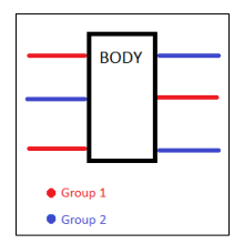
The train-inspired locomotion allowed us to actuate all 6 legs with only 2 motors. We did this by creating an alternating 1 up - 2 down gear train, so that at any given rotation, 3 legs were touching the ground, creating a stable triangle. To accomplish this long term - we had to make use of the encoders that came with the motors, so that we could monitor full rotations and sync the two motors for full actuation at any time.
Iteration 1
Iteration 1 was the first rough CAD drawing that we had for our project, and we made A LOT of changes as we went along. This initial model was only conceptual, but it explained a simple way to show how to articulate 6 legs with only 2 motors.
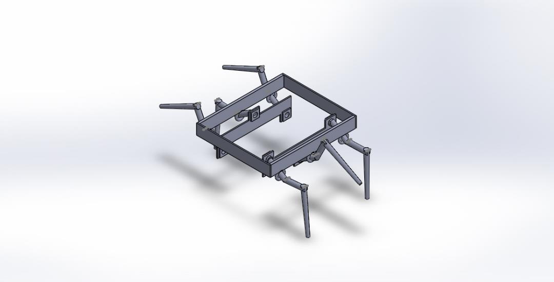
This design was then discarded for a 2nd design which we believed to be more stable.
Iteration 2
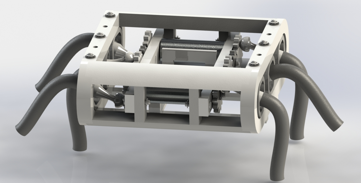
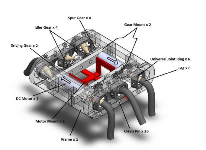
Iteration 2 began to look closer to the final product, it had a horizontal gear train system that used universal joints to create the oar-like movement we were trying to create with the legs. The chasis had three main parts for assembly, and ventillation holes in the base of the model for heat. The legs were curved to reduce the stress points, and ball socket joints were added to the legs and gears to create the rotational motion that we needed.
This design was much closer to the final design, and we took many of these concepts to the end.
Iteration 3
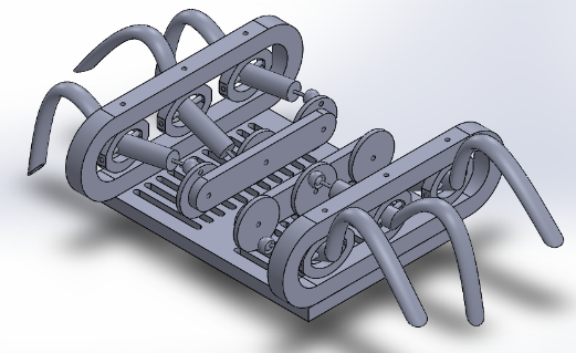
Iteration 3 was the final design that we chose. There was a total of 35 different parts and all were selected and modified to fit the final assembly. We created the most strained parts of the leg on the Objet 360 machine, and created the rest of the assembly on the Makerbot Replicator 2. By using both systems, we were able to maximize strength in areas that needed it, and reduce overall cost by printing everything else on the Makerbot Replicator 2.
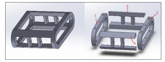
Because we now knew that we were sticking with this design, we had to alter parts to fit the final build volume of the Replicator 2. The Frame was seperated into 4 pieces (instead of 1), and male/female joints were added to increase strength in lateral directions. We then epoxied the frame and sanded the excess epoxy to create the appearance of a solid frame. We used this same technique with the two portions of the leg.
Assembly
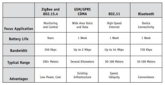
All other components/sub assemblies had to be created, assembled, and added to the final assembly. In tandem with creating the final assembly, we needed to work on communications with the hexapod from a wifi two-way connection. We weighed options between 802.11 IEEE standard, which can support mB worth of data (which we would have used if we had gotten to adding First Person View), but instead opted to use Xbee because of low battery wear and cost, as well as conforming to 802.15.4 standard without mesh networksing. Comparison to other communication types are below.
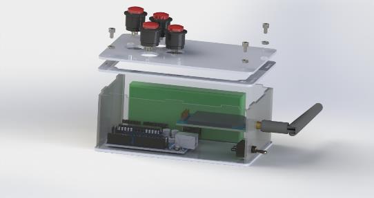
Communications
After selecting a communication type and preparing the PCBs/antenaes for operation, we had to create and assemble an entire controller, which we opted to house inside of an acrylic box. The transmittor and receivers were set up, and power switches were added to the hexapod and to the controller.
Test!
Finally, we were able to see our work come to life. We set it up and were able to play with our own Hexapod and a few weeks before presentation day.